CNC Router - Part 4/4
Setting up the closed loop stepper drivers, cutting the first project, and some upgrades to improve performance such as filling the tubes with grout.
CONTENTS
This is part of a 4-part writeup
Part 1 - Table and Prep
Part 2 - Construction
Part 3 - Wiring
Part 4 - Tuning and Upgrades
Tuning
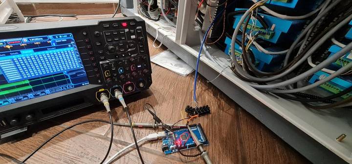
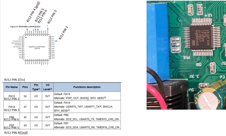
Since I'm using closed loop drivers, I also wanted to edit some parameters (particularly the holding current, how much offset it allows before throwing an error, and other things), but I had trouble communicating with the drivers since I had no programming cable, and about 4 different pinouts. After going down the rabbit hole for a while, I eventually was able to get communication with them using an arduino as a USB interface and the TX/RX lines directly. While the drivers say it's an RS232 connection, the pins go directly to the GD32F330C8T6 microcontroller so the voltages that RS232 uses are relatively unsafe for the 5v max that should be applied here.
It turns out that other closed loop drivers also use the GD32 series microcontroller (so far the few variations on drivers we've talked about on the Discord are actually the exact same model of microcontroller), so while the pinout to the 6 pin connector will differ, the PB6 (pin 42) and PB7 (pin 43) pins for TX/RX should be easy enough to identify. Checking continuity between the external pins on the controller and these two pins should give you the TX/RX wires.
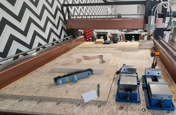
Testing and First Project
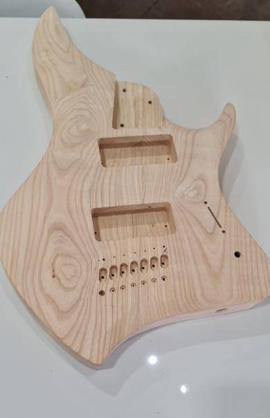
And the machine is mostly together, enough to make first cuts on my first project, a guitar body.
Replacing Homing sensors
I replaced my NPN NO homing sensors with PNP NC homing sensors, so that a break in the wire will trigger an error. However, I still ended up needing to use my pullup resistor block - just hooked up to ground instead of +24v to make it a pulldown.
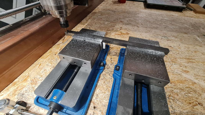
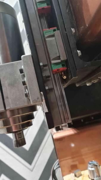
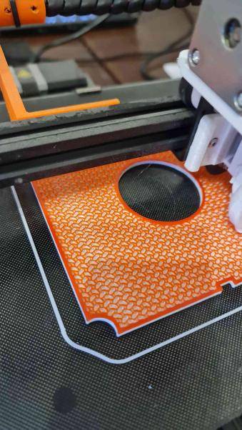
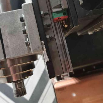
I also milled the steel spacer replacements and replaced the plastic spacers behind the Z axis. The plastic spacers are printed in two halves each, and each half I could bend like 10 degrees by hand, so having a one-piece full-length spacer out of steel makes a huge difference in rigidity (although quantifying it will take some more time as I haven't redone the weight tests)
Replacing Plastic Spacers
Grout Filling
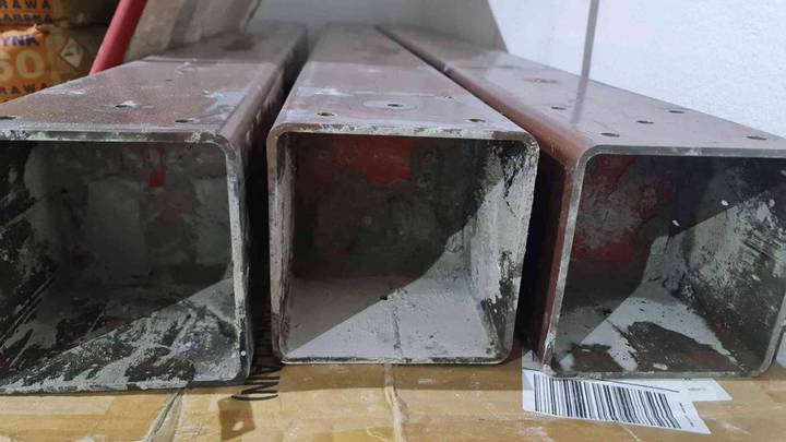
First printed some endcaps to fill the tubes with nonshrink cement mortar
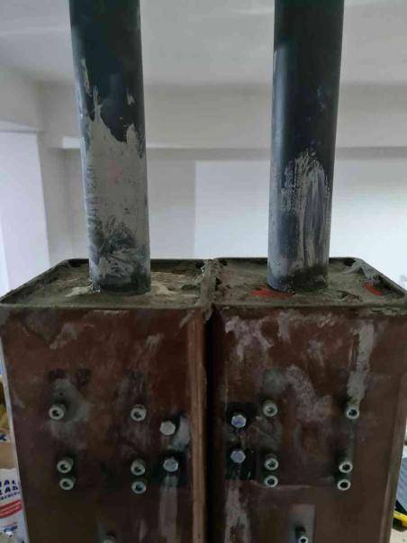
With the grout the tubes went from ~40 or 45kg each (without any attachments) to about 90 or 95kg each.
I also added the holes for the 150x150x10 angle iron at this time
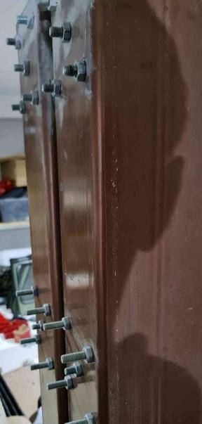
For the bolts, I just stuck bolts into each hole with threadlock on the face and tightened a nut against it to make pseudo studs. We will see how assembly goes. The crossmembers all have open ends to tighten nuts. If the bolts start spinning I will have to figure out how to keep them from doing so
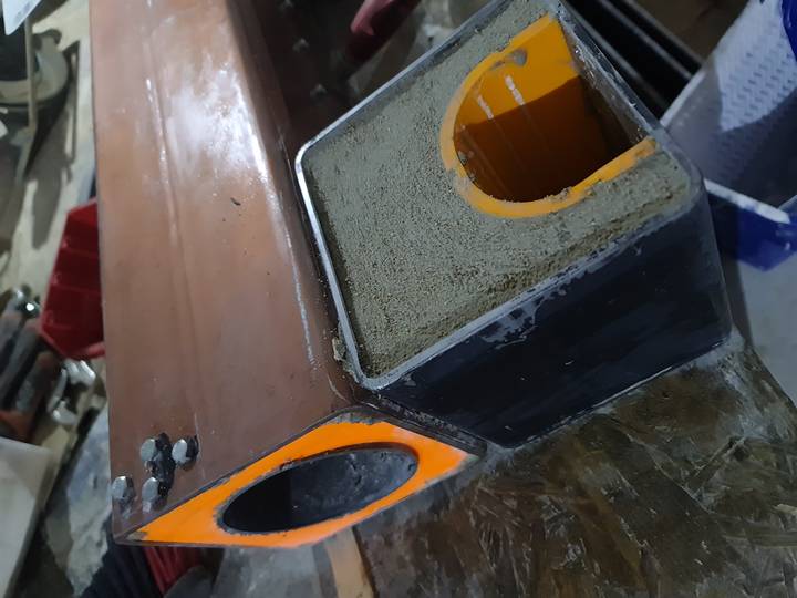
I filled both the rollers and the gantry. To keep weight down somewhat, I used a much larger inner tube for the gantry, and I used a 3d printed form to keep the grout away from the mounting points for the rollers.

