CNC Router - Part 2/4
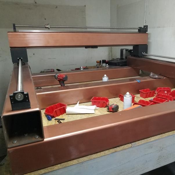
Cutting the steel faceplates for gantry rollers, spacers, installing rails and painting machine, and finally building the Z axis.
This is part of a 4-part writeup
Part 1 - Table and Prep
Part 2 - Construction
Part 3 - Wiring
Part 4 - Tuning and Upgrades
Steel Faceplates
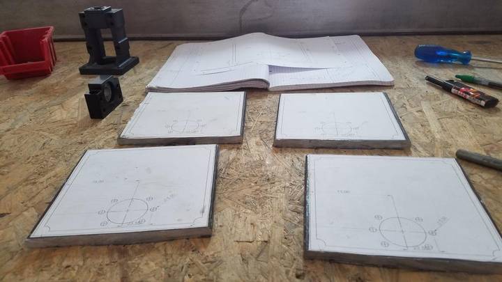
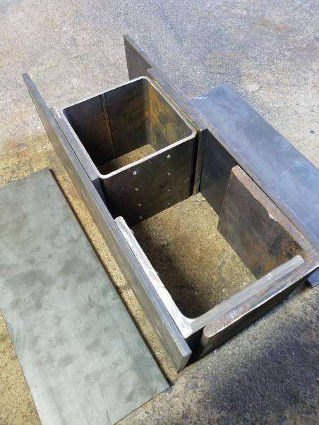
Since I'm basing my machine very closely off the PrintNC, I am using tube "rollers" for the gantry that require some kind of faceplates for the ballscrew nuts to press against. Given the size of my tube, the generally recommended 3d printed faceplates are going to be pretty poor for my machine, so I decided to make steel ones by hand.
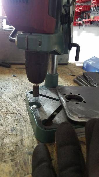
I printed some templates from the CAD model I had done, and used a very low-tech method of grinding away material in order to get the desired faceplate shape
Spacers
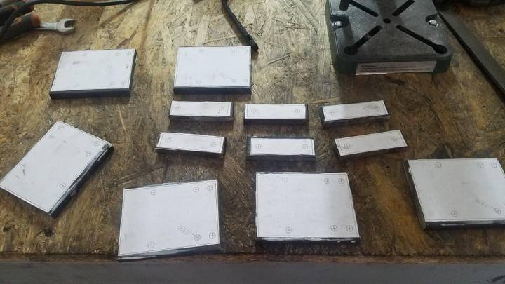
In addition to the faceplates, because I purchased HM mounts for my X/Y/Z motors, I needed some spacers to raise them up. I needed to raise them 30mm upwards, so I used three 10mm steel thick plates that I just stacked up to achieve it. Later on I can machine something a bit more precise on the router itself.
Installing Rails
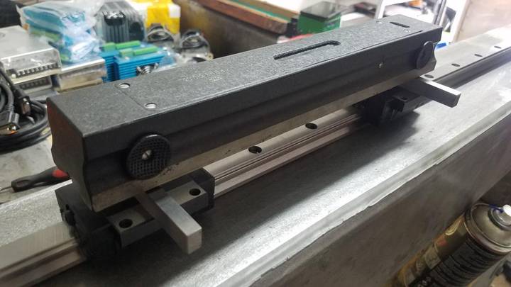
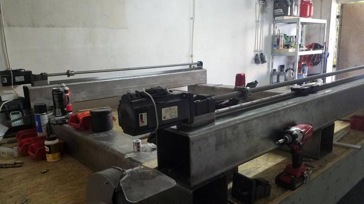
To ensure the rails were still leveled once I bolted them down, I put a precision level onto the HGW blocks. I used parallels since it was difficult to make sure I was taking into account the entire face of the HGW blocks.
Test Fitting Gantry
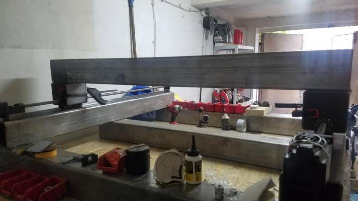
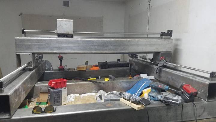
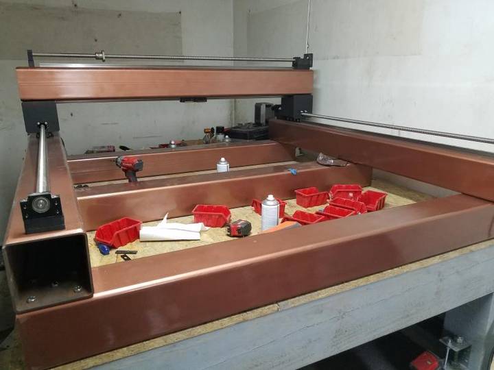
Now came the test fitting the gantry and rollers to ensure everything lined up properly, and then it was time to paint the thing!
Paint
Z Axis
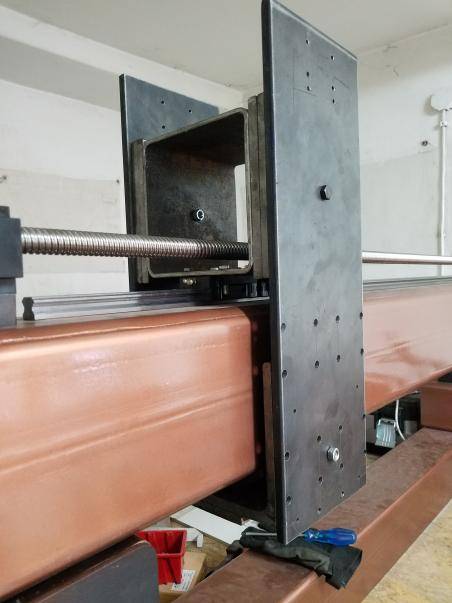
Then came the Z axis - since I wanted to have the Z axis mirrored on both sides, I already knew I had to make some changes. In addition, I needed some "spacers" that would go onto the X roller to allow space for the bolts on the backside of the Z axis
I also wanted to go with a "reverse" Z axis
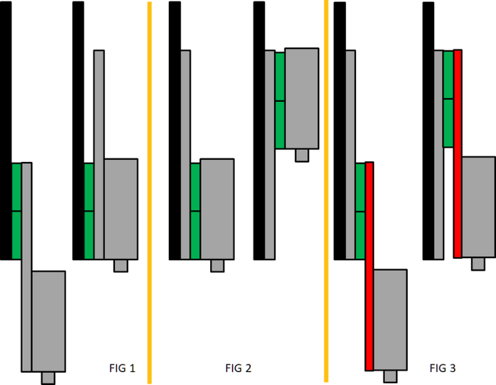
- In reverse rail situation (bearing blocks stationary, linear rail attached to moving part) (fig 1) your worst lever is at lowest point
- In normal rail situation (PrintNC design) if you try to keep similar level arm, you can't reach below gantry (fig 2)
- Ao when you try to achieve a similar drop by increasing tram plate length (fig 3) then its got a long lever both at the top and the bottom
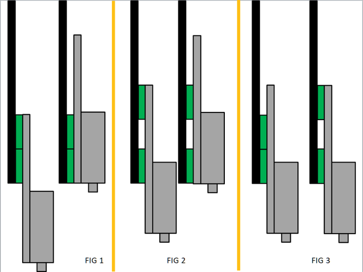
- So the 'reverse z' as mentioned in the last photo is here below (fig 1)
- By spacing out the bearings (fig 2) you reduce your overall travel but
- At that max travel with spaced bearings, the linear bearings will hold the spindle more rigidly than when spaced closer together (fig 3)
There's some math to figure out how far to space the bearings blocks, but basically the furthest you can space them while keeping your desired Z travel, the better. There are also pros/cons to both - neither one really gives you more "cutting" Z than the other, as the actual movement of the spindle will end up restricted one way or another, but this allows me to have taller objects that I machine the upper surface of comparatively.
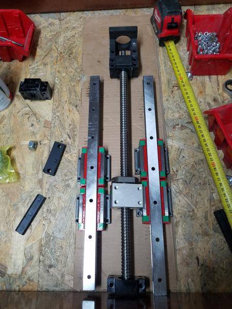
I started with a mockup of the Z axis.
Then I 3d printed some spacers to bring the rails up to match. I have 1605 ballscrews for Z, since I wasn't able to get the 1204 in the length I wanted including HM mounts for less than 1605 cost. In retrospect, the 1204 would've been preferable, as it pushes the spindle out a bit less overall
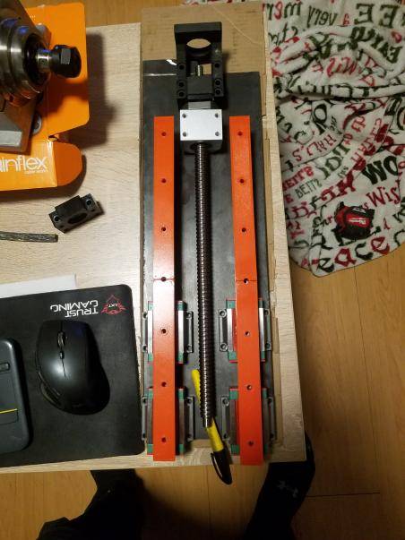
The mockup of how my Z axis will go together - the plates laying flat on the ground are the ones who the spindle is attached to (the tram plate in the stock PrintNC design)
And assembled. I went with a single bolt on top and bottom at first so that I could more easily square this piece up before pinning it with additional bolts.
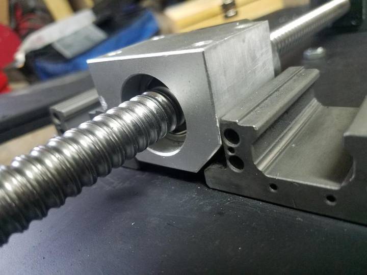
One problem I ran into that I didn't think about was using the HGW carriages for Z, which are a bit wide for the Z plate that I have. I ended up having to both shave down the aluminum nut block and the HGW carriages in order to get them to allow it to pass.
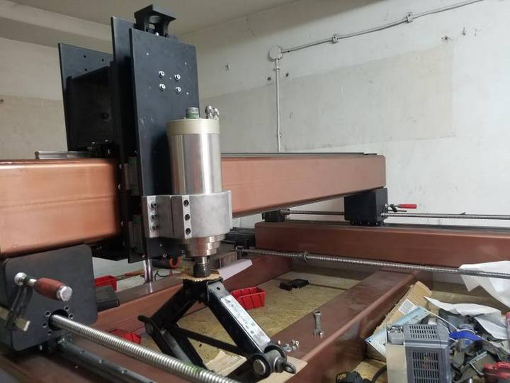
And finally attached - I ended up having to place the car jack underneath as the Z axis kept falling downwards otherwise, once the spindle was place on it.
I would've liked to add some "wings" to the Z axis to improve rigidity, but I think there's enough other weak points that it's fine for what I'm doing - I just need reasonable rigidity for what I'm doing and until I find it's insufficient I'll stick with this. I can also likely machine a better Z axis using the machine itself than I can make with some simple hand tools at that time.
