MACHINING GUITAR BODY
Click on any image for the full-size version.
For context, this was the first project that I completed after putting together my first router build.
Cut my first real project out of wood (back in September 2022), and learned a few lessons putting together the CAD/CAM for it that both I can continue to learn from but may also benefit others
CAD
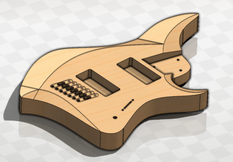
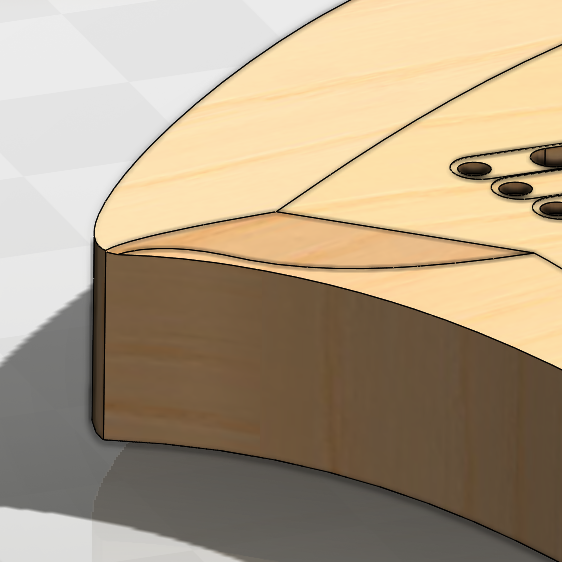
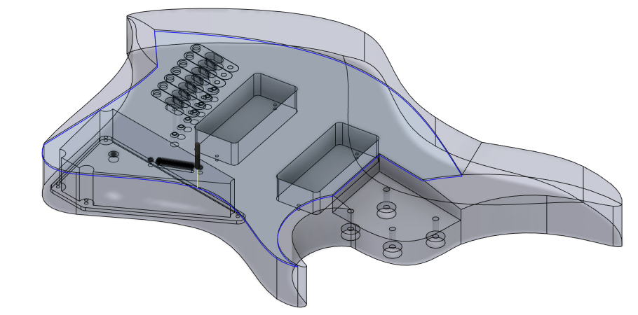
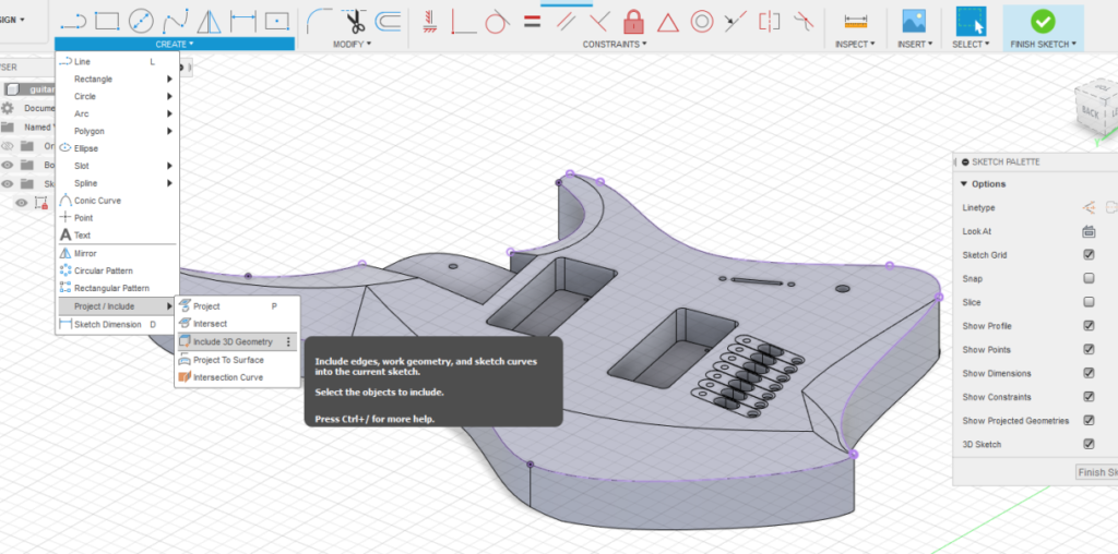
My friend actually did most of the CAD work for the guitar, but here’s what we learned. Our initial approach was to create the guitar in CAD software by starting with the external shape and extruding it. We then used a combination of 2D and 3D sketches to remove elements from the body and achieve our desired shape.
I don’t think this is a particularly effective method, as it gave us some trouble getting the “right shape” that we were looking for, although it was very easy to ensure that the neck was properly aligned.
On future guitars, I think our plan would be to first mesh model the guitar, and then use sketches to cut features specific to elements that require precise positioning (neck/pickups/bridge/etc) afterwards. It offers a bit more creative freedom without sacrificing the ability to make a model that can be used for CAM.
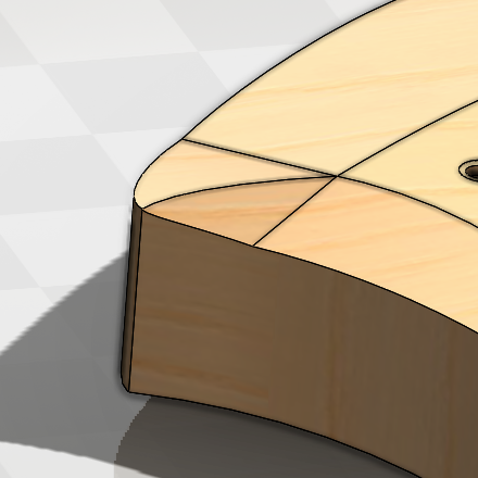
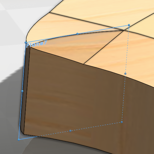
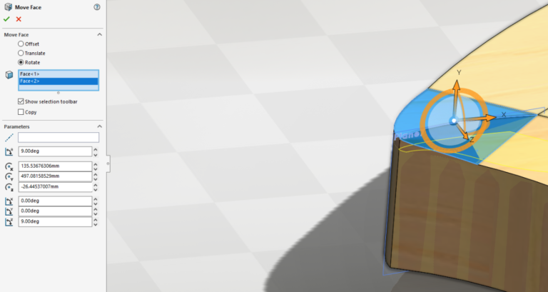
An example of where we ran into issues with our modeling path is pictured here on the left
Test Cuts
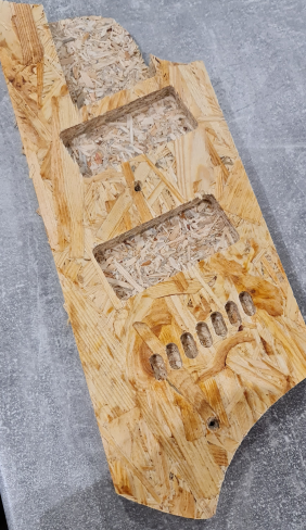
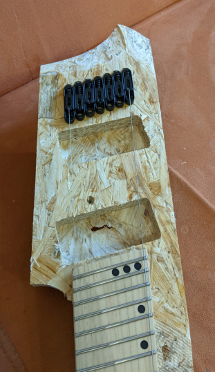
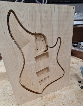
Once we had a working CAD model, I wanted to run some test cuts to verify the fitment of the existing neck that we had. In order to do so, I added a couple of reference planes to the model aligned with the neck and split the model so that we had only the relevant elements to cut. I reduced the overall thickness of the model to fit into some OSB that we had laying around as well.
I just screwed the OSB down (you can see two of the screw holes in the photo) to my baseboard and used a 2D Pocket and 2D contour to cut the features.
To ensure the screw holes wouldn’t interfere with the cutting, once I had stock loaded and probed I took a chamfer cutter at low RPM and touched the OSB in spots where there were no operations to ensure that the location wouldn’t end up inside a machining path.
We had a couple of adjustments to make since there were issues with alignment on the first cut, but once those were done I cut the same piece again but also included a 3D Adaptive toolpath with a ballmill (with a large stepdown) to get an idea of how the contours would end up looking.
CAM
8mm Operation
Since this was my first real CAM project, it was a fairly complex one and I learned quite a bit from it. Likewise, I didn’t get everything done properly this first time.
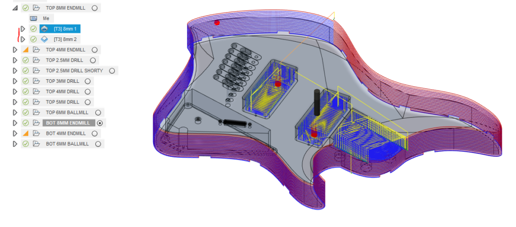
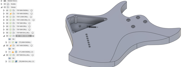
The first two operations I used an 8mm Endmill to rough out everything using a 2D adaptive toolpath for the 3 main pockets and a 2D Contour for the outside.
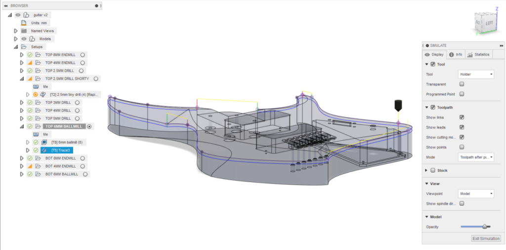
A few notes on the CAM, pictured here.
I was a bit scared (first project and all) so I used way, way too low stepdowns (1mm) across the board. This added immensely to the overall cut time and I regretted how long it took to cut.
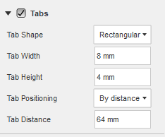
I also used some tabs (you can see at the bottom of the countour) which were quite thick. 8mm x 4mm was way to thick for this wood, and I would have been better with 6mm x 2mm or even less, with a larger space between them (maybe 120mm instead of the 64mm that I had used)
The other problem I ran into was that my contour was basically slotting the entire outside edge of the guitar. It was no issue higher up, but the endmill I used had only about 5mm more stickout than the deepest cut. It was difficult to evacuate chips from such a deep slot and it left scorch marks on the wood as a result. In retrospect, had I used even a 50% stepover during the contour it would’ve have prevented the endmill from rubbing the chips into the walls as it would’ve provided a place for the chips to go.
4mm Operation
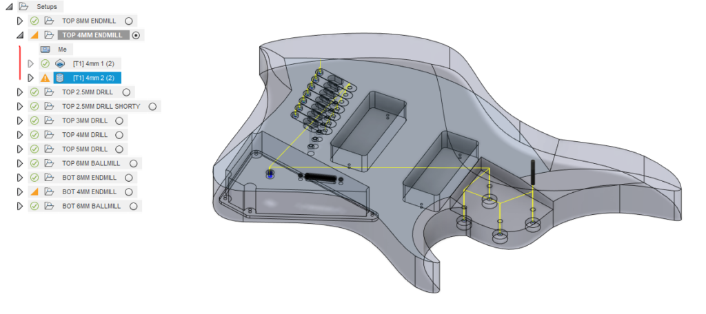
My next operation was to use a 4mm endmill to cut the smaller features. Here I made my first real mistake.
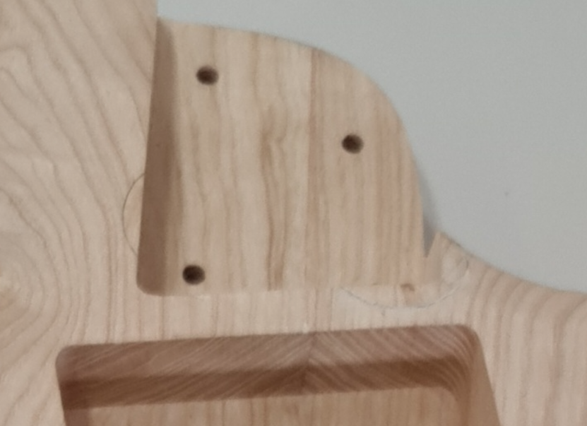
First, I didn’t make an operation that contoured the inside edge of pocket where neck fits into the body. The neck had an outer radius of 2mm. That 2mm inside radius in the body which would’ve been easily done using the 4mm endmill, but as I overlooked it I ended up having to manually adjust this fit.
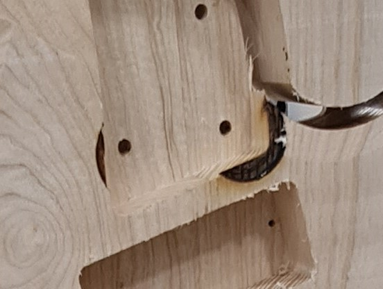
Second, I didn’t double check my endmill stickout with the depth of cut. Had I double-checked my G-Code preview or paid attention to the required toolpath, I would’ve noticed that I didn’t have enough stickout, but I didn’t.
Drilling and 3D Adaptive
Following the above operations, I did a bunch of drilling operations. At the time, I didn’t have endmills that were either long enough or thin enough (or both) to make many of the holes I needed. I didn’t use a center drill for these holes which ended up being a non-issue, but in a different material or harder wood it could have made a difference.
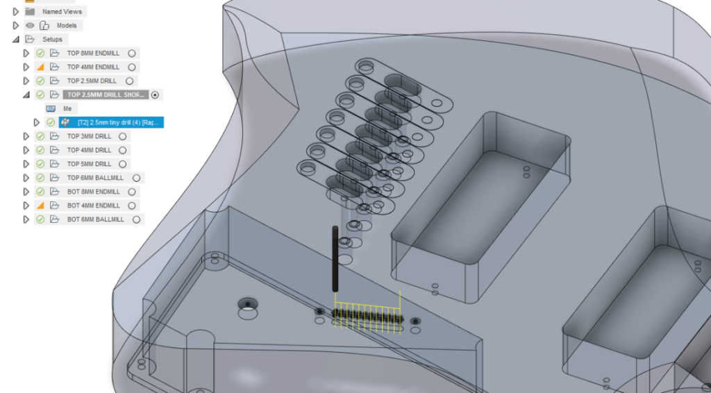
The most challenging feature to figure out how to cut was the 2.5mm wide slot in the face of the guitar. I ended up adding a sketch over this slot with equally spaced lines to make it easy to place a drilling operation at each intersection.
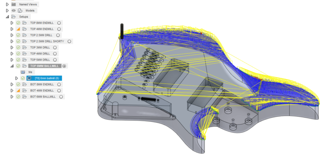
The final operation was 3D Adaptive for the contours.
3d Adaptive Lessons
Two things could have improved this:
First, using an 8mm endmill to rough of the major portions out would have made the whole operation much faster. I could have used the 6mm ballmill only to do the final surface, and it would’ve allowed me to use a much finer stepover while taking less total time.
Second, I didn’t use the “order by area” option. As a result, the machine spent a long time travelling back and forth over the whole length of the guitar body to keep cutting every element that occured at the same depth rather than finishing one area and then moving onto the next. I used a 1mm stepdown which came out quite nice with only about 1 minute of sanding, but a finer stepdown would’ve perhaps resulted in not having to sand the part at all. Alternately, if machining time was more of a consideration I could’ve used even a 2mm stepdown, since sanding would still not have taken very long to smooth the surfaces and the exact dimensionality of the curves is not important.
A Quick Tangent
 The next operations were on the bottom side of the stock, so it brings us to workholding, flipping the wood, ensuring it’s square, and keeping everything aligned.
At this time, I didn’t yet have a good solution for how to even square up wood to begin with, so I ended up placing the wood against pegs and tightening some square washers against them with some woodscrews. I machined the top side flat, then flipped it and machined the bottom face flat as well.
To square up the sides of the stock once the surfaces were flat, I cut the top half of all 4 sides, then flipped the wood and cut the bottom side to the same dimensions.
When I first did this process, the top and bottom halves of the stock did not match up at all. I had already trammed and squared my machine, but they were not matching by as much as 5mm at their worst point in the wood which was completely unacceptable. It turned out that my couplers for the motors to the ballscrews were slipping as I hadn’t cleaned the inner surfaces with alcohol or another degreaser prior to tightening them down. The weight of the gantry and relatively high accels were allowing slippage, resulting in the gantry coming unsquare.
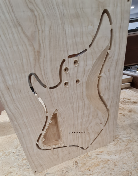
Once I resolved that machine issue, the top and bottom halves that I machined on the sides still did not align properly. While not nearly as bad, there was a mismatch of as much as 0.2mm (visible in the photo). I traced this down to the peg system that I had used, since wooden pegs allow some amount of flex, especially when they’re clamped against with the black square washers. Steel or aluminum pegs would’ve done a much better job – even broken endmills would make a good stand-in in this case, and would’ve allowed for better alignment.
My current practice to ensuring that the top and bottom are truly aligned though, is to use a 3D Touch Probe to actually probe the rotation of the stock. If the stock happens to be rotated by some small amount, I can rotate the G-code to match this rotation and ensure that the workpiece is cut squarely. I also think that using the black washers to clamp from the side ended up being to my detriment as well since it caused flex in the pegs that may appear even with aluminum or steel pegs.
I had also put screw holes offset from the edges of the wood by 10mm into each of the 4 corners that ended up working quite well, although I had also used the black pieces since I was afraid it would shift the stock when tightening the screws down.
Ultimately, workholding is a can of worms and there are likely other methods that are more reliable and effective.
2nd Side CAM
Result
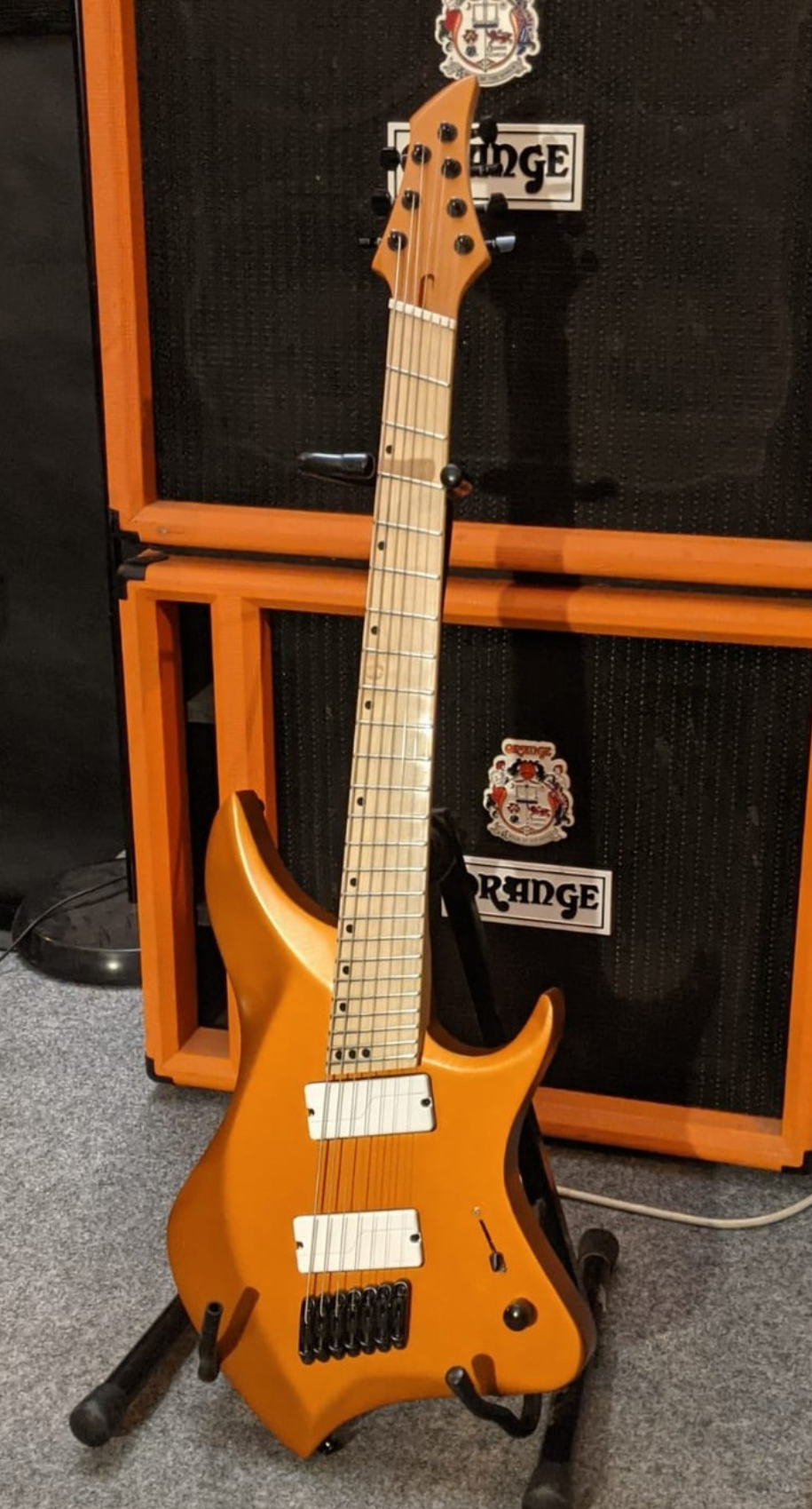
After running all the operations, I had my guitar cut out!
Fixing Mistakes
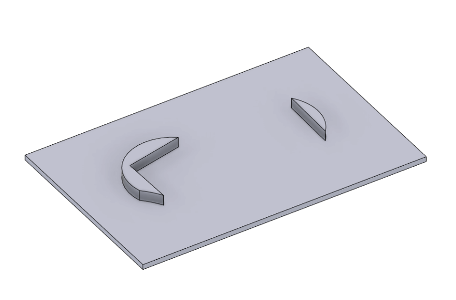
Since the nut has a known dimension, and I knew where the nut was centered when it burned into the neck, my friend modeled two pieces of guitar. I drew a thin plane underneath to “connect” the two piece together to make the CAM easier to accomplish.
I used a 2d Contour to recreate the cut I’d made with the 8mm endmill here into some of the spare stock and chiseled them off carefully.
A Note about Complex Chamfers/Filets
One feature that I had wanted to do, but wasn’t able to figure out at the time I cut it, was to add chamfer or filet directly to the outer contours of the guitar on the CNC machine.
We ended up manually sanding the filet into the guitar, which was a bit time consuming and could have been avoided had we done the steps below.
Main Takeaways
- Use surface modeling in CAD if you’re looking for free-form objects, as it offers a bit more ability to manipulate the object while making it possible to put into CAM
- When doing some hobby for a friend where your initial measurements and therefore CAD model may be suspect, slice the model into the “important” bits and make a test cut so they can test fitment before you cut the final piece.
- If you’re looking to just put a screw through the object to clamp it down, you can load the gcode into Linuxcnc and look at the preview from above, and move the toolhead to where you won’t be performing any operations and make it for drilling/screwing through.
- Too small of a stepdown makes everything take forever. Pay special attention to your helix down speed as well, which Fusion360 defaults to 333mm/min. If you have a large 2d contour it may try to cut the ENTIRE contour at this speed which takes way too long
- Tabs are great, but too large tabs end up being a pain to remove. I don’t know if there’s a good way to determine tab width/thickness as a rule of thumb, but mine ended up being overkill
- Check your depth of cut on the Gcode preview against your tool stickout – if something didn’t properly work in your CAM you can at least catch it here, otherwise you run the risk of putting the nut straight into your work
- Order by area instead of order by depth can help if you have a lot to cut and the machine will have to constantly rapid around
- If you do screw up, think about how you can use your CAD model to make pieces that will fit into it to fix it, since you can re-create exactly what happened in CAD with some math
- If Fusion won’t let you select on the area you want, make a 2d (for instance the multiple drilling operations for the slot) or 3d (for the chamfering I mentioned) sketch, project the splines/face that you want the operation to happen on, and then you will be able to select it in the Manufacture tab for CAM
- Add some roughing pass to contour so he doesn’t have to slot the outer contour of the wood

