Robot Tank - Part 1/2
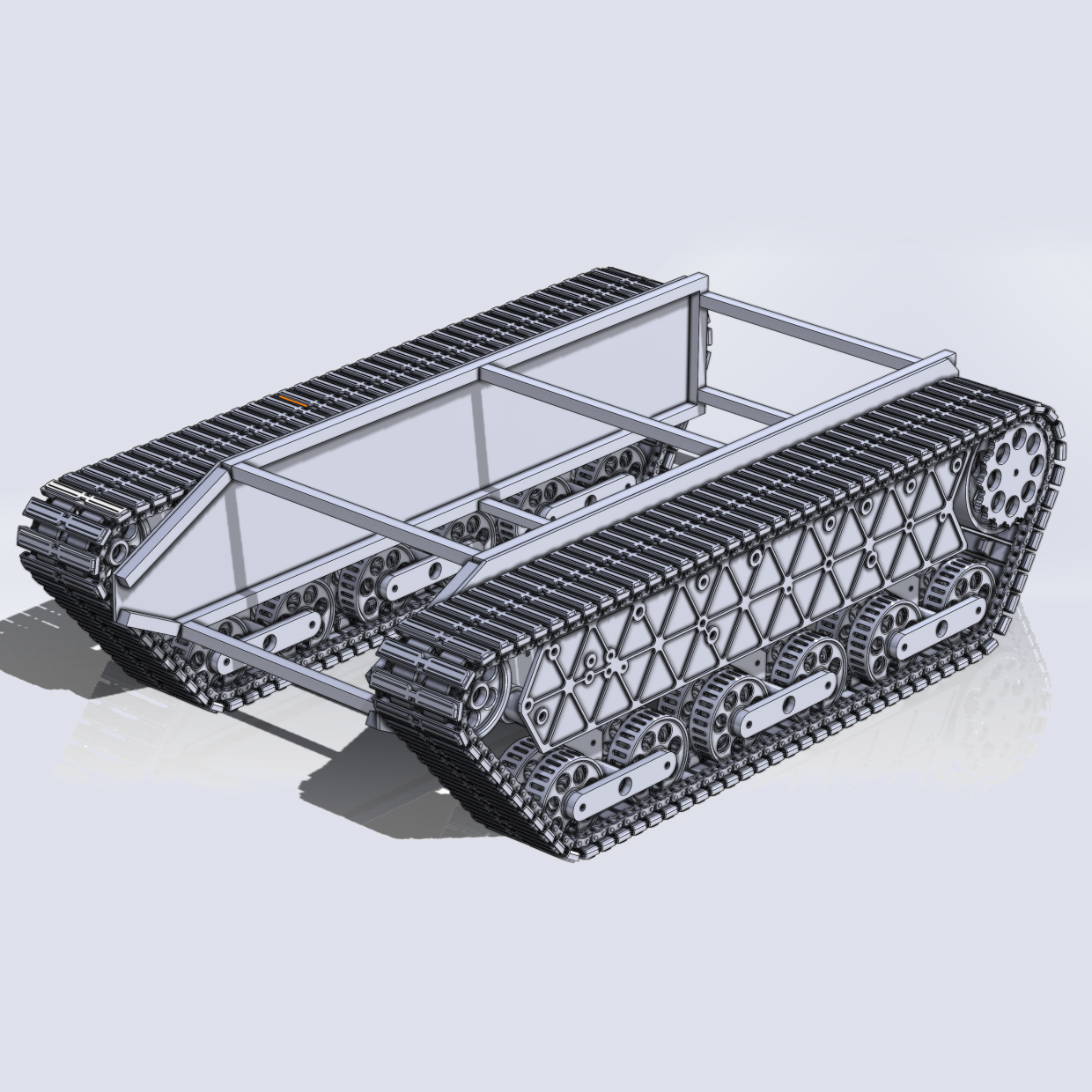
Project log for a large robot tank platform that I built. Part 1 covers the design considerations and process for the robot tank.
CONTENTS
I needed a large robot for another project, so I figured why not a huge robot tank. It would be a fun project and offer a lot of flexibility for future projects using it as a platform.
See Also: Part 2 - Construction and Assembly
Initial Design
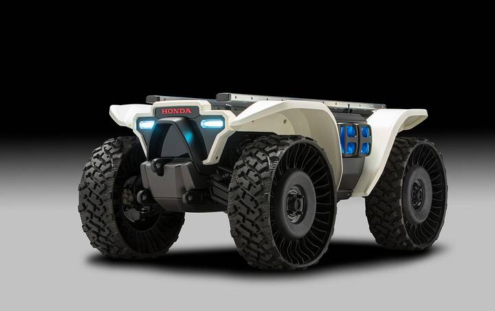
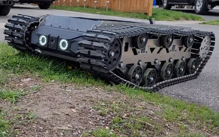
In the initial design phase, I considered a variety of robot platforms, including two-wheeled and four-wheeled holonomic and non-holonomic platforms, as well as drones. Two existing implementation that I found particularly interesting are pictured here below. On the left is a Honda 3E-D18 ATV and the right is another DIY robot tank I saw on YouTube.
A robot using mecanum wheels was also pretty interesting for me due to its maneuverability. Ultimately, I just wanted a platform that could carry a reasonably large payload and work for a variety of future projects, so I knew that I wanted to build either an ATV or a robot tank.
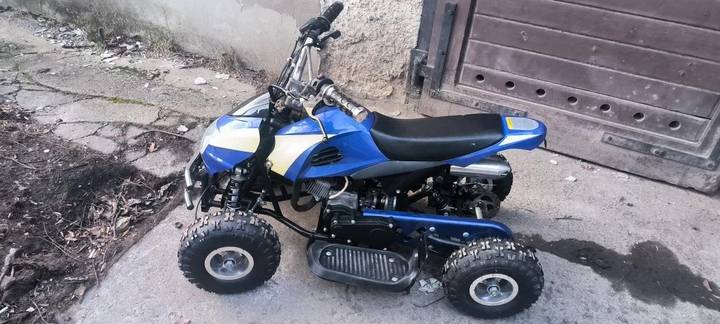
I actually found a suitable chassis from a broken mini-ATV locally that I could've used to make an autonomous ATV from, and it was priced very inexpensively. The broken motor wasn't an issue as I would be replacing it with an electric drivetrain anyways to be easier for control. However, the "call of the void" so to speak of building a robot tank was too strong to resist, so I pursued that option instead.
Another advantage of the robot tank when making it autonomous later on is that a robot tank uses a much simpler differential drive mechanism, compared to the steering of an ATV, so building a control for it would be much simpler to implement.
Requirements
So having settled on building a robot tank, the next step was figuring out what I wanted for requirements. I somewhat arbitrarily chose these, but was happy with them in the end.
- A length of about 1 meter
- Width of less than 800mm to ensure it can drive itself through most standard doorways
- Ground clearance of at least 15cm for small obstacles
- Suspension travel of at least 10cm
Yeah, I wanted my robot tank to have a suspension too. It raises the complexity a little bit but it seemed silly to spend all the time building a custom robot tank and not include it as well.
Design Process
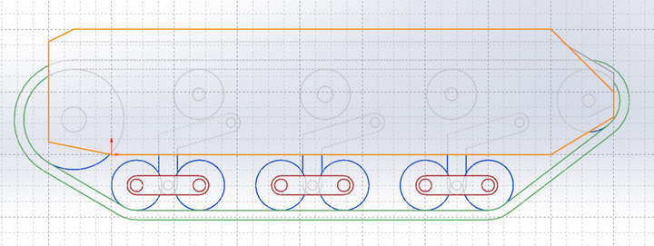
The size of the robot tank gave me quite a lot of room to fit everything that I'd need, like batteries/motors/etc, so the overall process is pretty straightforwards. Instead of worrying about how I would fit components, I focused on the overall shape of the robot itself only, and came up with my initial 2D sketch for how I'd like it to look over the course of a few iteratinos
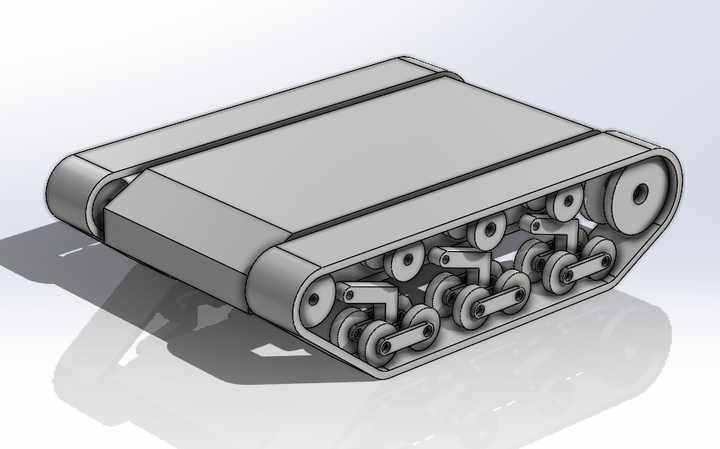
I then took the 2D sketch and turned it into a block diagram of the major components.
Seeing it in 3D helped me identify a few issues that I needed to resolve - namely that the wheels are too narrow, and as a result there is also no way to keep the tracks from sliding off in a simple way. Also, I determined that the size of the rear sprocket was quite a bit too large in comparison to the rest of the tank and would end up hitting on the suspension components when they compressed.
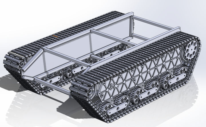
A few more iterations and I settled on a more finalized design.
Frame
I built the frame by cutting and welding some tube steel into the right shape. I used 20mm tubing as it has plenty of space for mounting screws, bolts, and anything else I may add without adding too much bulk or weight to the final robot. To cover the frame, I ended up using HDF (high-density fiberboard) as it was cheap and easy to cut into shape. Later on I'd like to replace this with some sheet metal.
Suspension
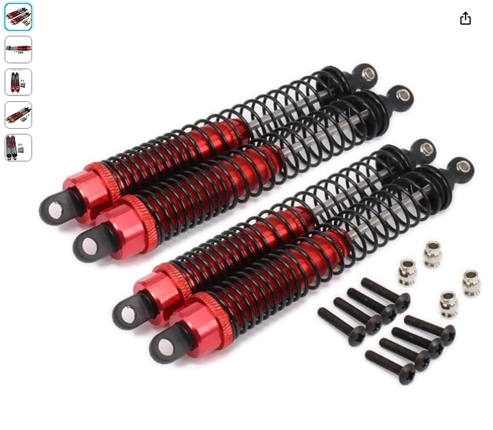
For the suspension, I used some RC shocks as the base, and wound some custom springs to increase their capacity over what they were intended to be. I used two of these RC shocks per wheel quad, 12 in total for the entire tank. Actually figuring out what gauge of wire to use and how to wind it was a math problem that took a bit to solve.
Track Feet
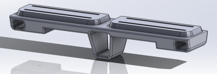
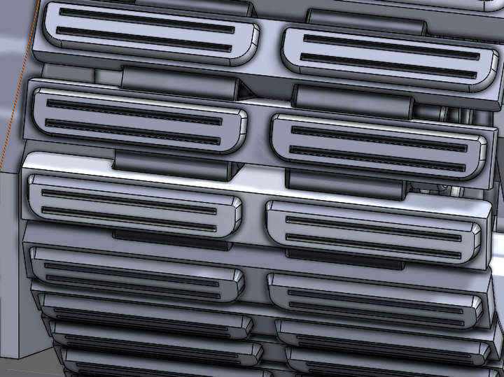
I wanted to make the tracks stay on the robot tank, so I designed some track feet with lugs that hold them straight and keep them from falling off. They're intended to be 3D printed, and I hollowed out various sections with some prototypes until I found a decent balance between strength and the amount of resin required for each one.
I designed the track feet with four 1.75mm gaps in them, either to potentially grab the ground a bit better on dirt or to press-fit TPU 3D printing filament into them. However, after realizing how many track feet that I needed and how much time it would take to cut and press in that many pieces of TPU, I abandoned the idea for now. Luckily, it isn't really an issue as the feet are already grabby enough on the ground without the TPU inserts.
Behind the track feet, I am using chains - similar to the robot tank that I had seen on YouTube. It's simple and it works quite well.
Track Layout
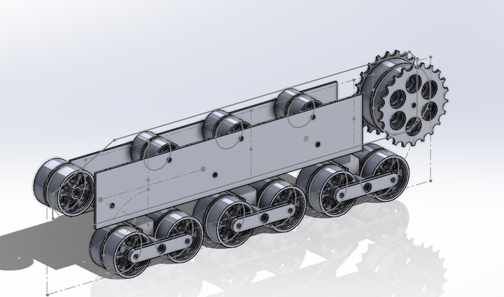
For the track layout, I aimed for a design that would provide stability and traction while allowing for smooth movement. The final configuration consists of twelve roadwheels, six idler wheels, one tensioner with two additional idler wheels, and two drive sprockets, all mirrored along the central axis of the track.
Each pair of roadwheels is connected by a central axle, and these pairs are further linked to a single suspension arm with two springs per arm. This arrangement allows each group of four roadwheels to rotate freely around their central axis, with only the deformation of the overall track providing any constraint. The result is a flexible system that can absorb bumps and irregularities in the terrain.
However, there's still room for improvement. One thing would be to reposition the suspension arm connection points on the front and rear roadwheel pairs. By shifting them forward and backward respectively, I could ensure that more force is applied to each pair of roadwheels as the track goes over obstacles. This adjustment would also help maintain a more angular track design which looks better, while keeping equal pressure on all wheels.
Wheels
When designing the wheels for the robot tank, I wanted reasonable strength with minimal material usage. Through iteration, I was settled on the wheels seen above with many holes and nearly completely hollow design that I wanted to 3D print.
To make the wheels work well with the track nubs to hold the tracks on and ensure good weight distribution on the feet, I made the roadwheels as wide as possible. Each wheel features a central hub with enough space for two bearings and the pass-through hole for the axle.
Motor Coupling
I considered a motor with a gearbox, as it would've offered significant torque, but after looking at various options I ended up choosing hoverboard motors as they are already pretty ridiculously torquey given their size, very inexpensive, and also have quite high max rotational speeds. I guess it's not surprising as they're intended to move people around.
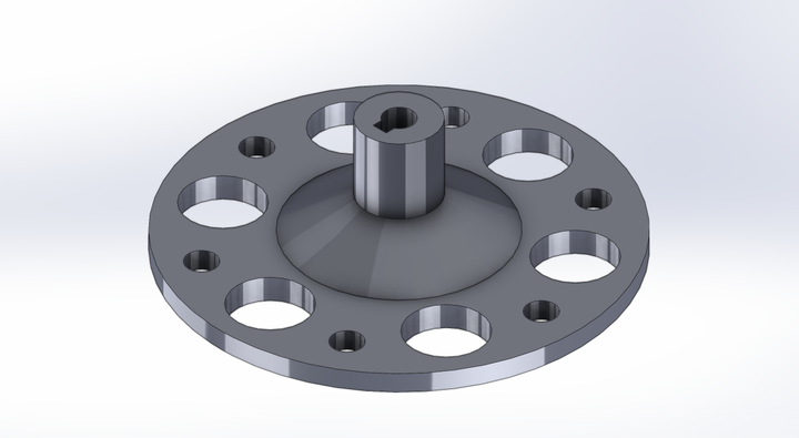
In the first iteration of the motor couplers, I thought I would be able to get away with just clamping the motors onto the axles using a compression coupling, but it was clear that it wasn't sufficient. Instead, I ended up making some couplers that I bolted to the face of the hoverboard motors and used a keyway axle to transmit power to the drive sprockets.
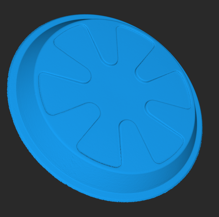
To make sure that it fit, I used a 3D scanner to digitize one of the hubs and used this to reverse engineer the matching couplers.
Drive Sprockets
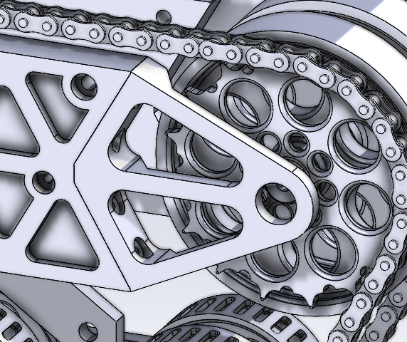
The sprockets themselves also originally relied on some compression fitting with a cotter pin, but it became clear that was insufficient, so I also changed this to use keyways as well. I used some size 08B chain instead of bike chain to have something wider that I could screw the track feet through on the backside, and planned on using a 3D printed sprocket. While I would've been better to use a machined sprocket instead, I'm glad that I went with 3D printed as I ended up going through a few iterations of the design before being satisfied.
I also found that I needed to add an external support onto the back of the outer covers, to ensure that the drive sprockets stayed centered without shifting around.

